Audio tesla tl494 ir2110 high power pwm cycle schematic circuit diagram. When creating a crystal tester circuit is complete.
 Crystal Tester Circuit Electronic Schematics Circuit
 With an intact crystal the dc voltage at the base of the transistor t2 is high enough to cause the transistor to conduct.

Crystal tester circuit schematic diagram. So it can be soldered onto the perforated board easy to save money and time. Some circuits would be illegal to operate in most countries and others are dangerous to construct and should not be attempted by the inexperienced. First get a good crystal to test in the circuit.
Pcb designer pic power amplifier power guard power supply preamplifier circuits protection schematics radio circuits regulator diagrams rf schematics sensor circuits tester circuits timer circuits. Here is the schematic diagram of the circuit. Test equipment circuit diagrams and electronic projects.
The oscillator will produce a high frequency signal if a good crystal is connected at the testers probes. The led lights up signalling that the crystal is good. Then press s1 to see the led1 brightness.
The crystal tester described here will quickly show skip to main content. Many circuit uses crystal as a important component to oscillate signals these signal are main requirement for other device in the circuit if the crystal got damaged means we can not easily test the crystal without any oscillator circuit to avoid this situation here we given simple crystal tester circuit. Circuit diagram for crystal tester.
The electronic circuit cand be used to test crystals with frequencies from 100khz up to 30mhz. Crystal tester circuit schematic diagram see more about crystal tester circuit schematic diagram crystal tester circuit schematic diagram. Crystal tester circuit diagram.
Note that all these links are external and we cannot provide support on the circuits or offer any guarantees to their accuracy. The circuit is simple and easy to build here is the schematic diagram. A very useful project of a crystal tester circuit or xtal tester circuit built with only few components the circuit form an oscillator that will only oscillate if the under test crystal is in good working condition and the oscillator output voltage will be rectified by 1n914 diodes and filtered by 01uf capacitor and reach.
The current consumption is low. Stk428 610 anfi project pt2317b preanfi top249y 2x30v smps schematic circuit diagram. Quartz crystal tester schematic circuit diagram.
Next remote control for network devices schematic circuit diagram. This crystal tester circuit use only two transistor the first transistor is used as an oscillator and the second one is employed as the detector. This project use equipment less.
But if it goes out showing. The mechanism of this crystal tester is very simple. Transistor q1 and the crystal under test from an oscillator.
How to build crystal tester circuit. It is the test circuit. A crystal tester circuit is very simple it contains only oscillator and detector inside.
This crystal tester circuit uses one transistor for the oscillator and one transistor for the detector.
Dave S Homemade Radios Visitors Page G0cwa Crystal Tester  Two Terminal Bipolar Power Supply Analog Devices
 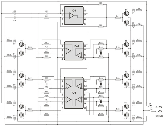 Operational Amplifier Tester Circuit Electronics Projects
  Author Topic Crystal Tester Using A Vacuum Tube
  Test Equipment Circuit Diagrams And Electronic Projects
  Figure 4 From Low Cost High Performance Microcontroller
 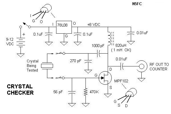 N5ese S Crystal Checker
  Crystal Tester 1hz 50mhz Diy Kit Manual X4e65vqeymn3
  Quartz Crystal Oscillator And Quartz Crystals