Learn to navigate this systems wiring circuitry and diagram using current flow analysis relay and module operation and neutral switch actuation such as circuit completion. It will keep power on from the nc terminal to your run circuit unless you have a safety condition on oil pressure or coolant temperature.
 7a68 221 Murphy Switch Wiring Diagram Epanel Digital Books
 This indicates either an open circuit unwanted grounds or too high resistance in switch loop circuit wiring between sw1 and sw2.

Murphy switch wiring diagram. Magnetic switches and tattletale annunciators. Typical wiring diagrams. Fw murphy continues to provide a full spectrum of engine management solutions.
Typical wiring diagrams in order to consistently bring you the highest quality full featured products we reserve the right to change our specifications and designs at any time. Start switch alternator to magnetic sensor alternator tach terminal or signal generator b energized to run pb128s stop switch starter s b exciter r fuel valve typical wiring diagram with 760a and 761aph g no r nc sw1 sw2b 518ph jumper b sig grd distributor ignition coil fuel valve rack pull solenoid rp2300 series shown. These range from electronic and mechanical controls to custom engineered compressor control panels and systems plus turnkey ignition systems and air fuel ratio control systems.
View and download murphy tattletale wir 97020b wiring instruction online. Figure 2 shows a closed loop circuit with normally open murphy swichgage instruments and normally closed switches alignment and v belt switches etc. 117 117ph tattletale ms2100 tattletale 518ph 760a 761aph.
Typical wiring diagrams figure 2 shows a closed loop circuit with normally open murphy swichgage and v. See how the anti. Tattletale wir 97020b switch pdf manual download.
Murphy wd 8198b wiring diagram wd100 series panels wd100 wd150 wd175 wd185 518ph tattletale magnetic switch with mechanical swichgages this is a basic energize to run panel. Start switch alternator to magnetic sensor alternator tach terminal or signal generator b energized to run pb128s stop switch starter s b exciter r fuel valve typical wiring diagram with 760a and 761aph g no r nc sw1 sw2 b 518ph jumper b sig grd distributor ignition coil fuel valve rack pull solenoid rp2300 series shown. Start switch alternator to magnetic sensor alternator tach terminal or signal generator b energized to run pb128s stop switch starter s b exciter r fuel valve typical wiring diagram with 760a and 761aph g no r nc sw1 sw2 b 518ph jumper b sig grd distributor ignition coil fuel valve rack pull solenoid rp2300 series shown.
 Wiring The Murphy Way Enovation Controls Help Center
  Install Wire Troubleshoot Fw Murphy W Series Engine Panels
  Murphy Wiring Diagram Wiring Diagram
  Murphy Switch Wiring Diagram Ignition System Distributor
Murphy Switch Wiring Diagram Ignition System Distributor  Murphy Wiring Diagram Wiring Diagram
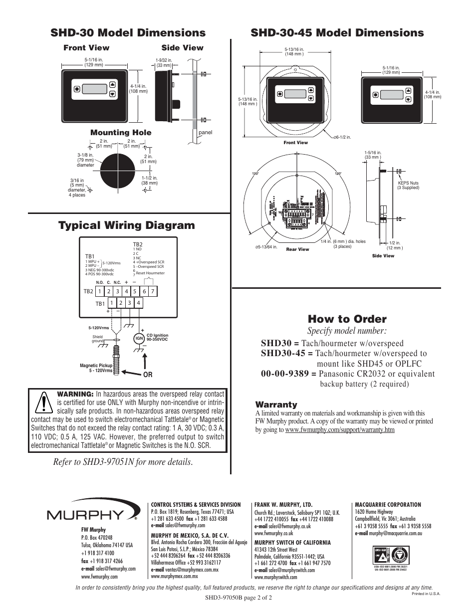
  Typical Wiring Diagram Shd 30 Model Dimensions Shd 30 45
  Vw Light Switch Wiring Diagram Wiring Diagram
  Reliance Wiring Diagrams Wiring Diagram
  Wiring Diagram Mag Lock Biometric V1 6 In Magnetic Door