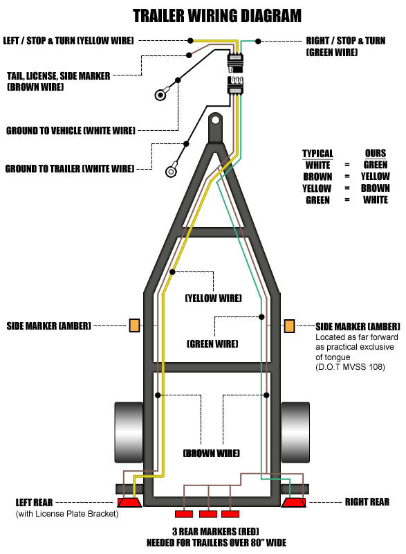
Trailer Wiring Diagram Ground Vs Negative

Trailer Wiring Diagram Ground Vs Negative

Trailer Wiring Diagram Ground Vs Negative. Ground neutral and hot wires explained. Finally, disconnect the ground wire and attach it to a piece of wire that runs to your car's negative battery terminal.

Trailer Wiring Diagram – Lights, Brakes, Routing, Wires ...
Trailer Wiring Diagram – Lights, Brakes, Routing, Wires ... (Isabel Gregory)
Video tutorial on how to wire trailer lights. When plugging in a grounded appliance or other device, the ground wire gets attached to the chassis. You also need a ground wire.

Anyway, the ground wire should only carry current in the case of a fault condition.

Why is it that this lead is sometimes referred to as the In the case of DC systems, the negative terminal (typically) is generally grounded for simplification in wiring.

How-to: Upfitting an equipment trailer with back-up lights ...

Wiring Diagram For Trailer Light 7 Pin ...

Pollak 7 Way Trailer Connector Wiring Diagram | Trailer ...

2003 Dodge Ram 1500 Trailer Wiring Diagram | Trailer ...

6 Volt Positive Ground Wiring Diagram | Fuse Box And ...

123Ignitionusa LLC

Pollak Trailer Wiring Diagram | Trailer Wiring Diagram

Positive ground vs Negative Ground - Which manual is ...

TC-4CMPT 4-Wire Male Trailer Light Connector | Super ...

So, it is a danger only when you are standing in the basement in water, or when something is not working elsewhere. We were having a discussion today at work about positive ground vs. negative ground electrical systems in cars. After explaining and diagramming it, he builds the circuit on a scrap piece of copper clad board and puts it through some benchmarks to prove it Electron Current vs.

Share:

Posting Lainnya:

Disqus Comments